Battery Maintenance for a Race Yacht
On a canting-keel boat the battery bank feeds the electro-hydraulic keel pack, whose peak current spikes on every cant. This is the electrochemistry — sulfation, lithium plating, Peukert derating, terminal resistance — and the maintenance regime that keeps state of charge and internal resistance where the keel can rely on them.
11 min read
On a canting-keel race yacht the battery bank is not a convenience — it feeds the electro-hydraulic pack that swings and locks the keel, so its state of charge and internal resistance are safety-critical numbers. A flat house battery on a cruiser means a cold breakfast. On a boat like the Melges 40 the same failure can mean a keel you cannot centre and lock. That single fact reframes every task below, from the charge algorithm down to the torque on a terminal nut — and it changes which electrical parameter you actually maintain for.
Why the battery is a critical system, not a background chore
The electrical system on a canting-keel boat carries three loads: the keel hydraulics, the instruments and processors that drive your polars and VMG targets, and engine starting. The instruments are a low, steady background draw — a few amps. The keel pump is nothing like it: a hydraulic power pack pulling a large, brief current for the few seconds it takes to swing the fin across the boat on each tack and gybe. Publicly the Melges 40 is described as running its canting keel off two batteries with an electro-hydraulic pack sized to cant fast enough that a gybe is no slower than on a fixed-keel boat, and to leave roughly 60 per cent capacity after three races — but treat those as class-literature figures to verify against the boat's own documentation, not design targets.
What matters for maintenance is the shape of that load, not its average. A short, high-current pulse is exactly what exposes a tired bank, because the voltage the pump sees is the open-circuit voltage minus the current times the internal resistance of the whole DC path — battery, terminals, cables, switch, fuse. Double the effective resistance and the rail collapses further on every cant, the pump slows, and the fin lags the boat through the manoeuvre. So you maintain this bank for two numbers: state of charge, which sets the reservoir, and internal resistance, which sets how far the rail sags when the pump asks for its worst-case current. Manage those and the steady electronics load has enormous margin underneath.
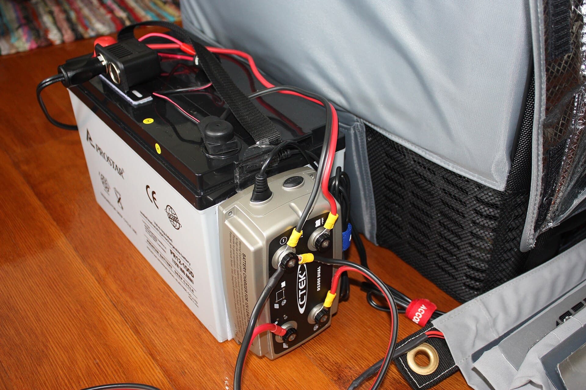
Chemistries: AGM versus lithium, and why the regime changes
Most race programs run either AGM (absorbed glass mat lead-acid) or LiFePO4 lithium iron phosphate. The difference is not just weight — it changes the physics you are maintaining against.
AGM immobilises the electrolyte in a glass-mat separator, so it is sealed, spill-proof and vibration-tolerant, and takes a conventional lead-acid charge. Its penalties are mass, a usable window that really wants to stay above roughly 50 per cent state of charge, and — the one that bites a keel — internal resistance on the order of 10 to 20 milliohms per battery, rising further as it discharges and as it gets cold. Under a hard pump pulse that resistance is what sags the rail.
LiFePO4 carries far more usable energy per kilogram, holds a flat ~3.2–3.3V-per-cell discharge plateau under load, and has internal resistance closer to 5 to 10 milliohms — so the rail barely moves when the pump fires, and it recharges at high current without complaint. On a weight-critical Grand Prix boat, where the bulb already carries most of the ballast, an integrated lithium battery system recovers kilograms you would rather spend as crew or lead. In return it demands a battery management system, a lithium-specific charge algorithm and hard temperature limits. Whichever chemistry your boat runs is a fixed design choice; the discipline is to maintain each on its own terms and never share a charger between the two without correct, chemistry-matched settings.
Charging: the algorithm is the maintenance
AGM wants a three-stage lead-acid profile: bulk (constant current, pushing amps in while voltage climbs), absorption (constant voltage, held near 14.4 to 14.8V at 25°C while current tapers toward a small "tail"), then float near 13.3 to 13.8V to counter self-discharge without gassing. The step most programs get wrong is temperature compensation. Lead-acid set-points must move roughly -3 to -5 mV per °C per cell — about -24 to -30 mV/°C for a 12V, six-cell bank — so a bank charged to a fixed 14.6V in a cold cabin never saturates and sulfates, while the same set-point in a hot engine bay overcharges and gasses. Use a charger with a battery temperature sensor on the case, not on the alternator. AGM should generally not be given the 15.5–16.2V equalisation used on flooded cells unless the manufacturer explicitly calls for it; that regime is designed to boil and remix a liquid electrolyte AGM does not have.
LiFePO4 is simpler and stricter: constant-current bulk to a constant-voltage hold near 14.2 to 14.6V (about 3.55 to 3.65V per cell), then stop. There is essentially no float — a lithium cell parked at a lead-acid float voltage is being held hard against its top plateau, which stresses it and, over time, can promote plating; most BMSs simply drop the charger out once absorption current tails off and let the pack rest near 3.4V per cell (~13.6V), re-bulking only if it falls to about 13.2V. Lithium must never see desulfation, equalisation or reconditioning modes; those are lead-acid concepts.
The failure mode either way is a single charge source set for the wrong chemistry. Audit every source against the installed cells — shore charger, alternator regulator, DC-DC, solar controller — because it only takes one misconfigured input to slowly cook a bank. And treat the exact numbers above as typical industry ranges: the authoritative set-points come from the cell datasheet and the boat's own documentation.
State of charge and sulfation: the lever that sets lead-acid life
For AGM, state of charge is the single biggest determinant of lifespan, and the mechanism is worth understanding because it dictates the rules. On discharge, both plates convert to lead sulfate, PbSO4. Recharge normally reverses this — but if the bank sits part-discharged, the fine PbSO4 crystals undergo Ostwald ripening: small crystals dissolve and redeposit onto larger ones, growing a coarse, electrically inert sulfate phase with far less surface area. That coarse phase resists reconversion on the next charge, so it permanently removes active material, lowers capacity and — critically for a keel — raises internal resistance, deepening the very rail-sag you are trying to avoid. This is why cycling to about 50 per cent depth of discharge can yield on the order of a thousand cycles while routinely pulling to 80 per cent roughly halves that: the deeper and longer the discharge, the more of the sulfate coarsens irreversibly.
The rules follow directly. Recharge fully after every session so crystals stay fine and reversible; never store a bank flat, above all over a layup, where weeks at low charge is exactly the ripening condition; and treat a chronically low reading as a fault to trace — a source under-delivering or a parasitic load — not a number to live with. LiFePO4 has no sulfation and tolerates partial cycling happily, but dislikes prolonged storage at either extreme; a mid-range storage charge, roughly half, is kindest to calendar life.
Peukert and temperature: why cold and heavy loads shrink the reservoir
Two effects make a lead-acid bank deliver less than its nameplate exactly when the keel needs most. First, Peukert's law: usable capacity falls as discharge current rises, because higher current wastes proportionally more energy in internal resistance and outruns acid diffusion into the plate. The Peukert exponent k is about 1.05 to 1.15 for AGM (and 1.2 to 1.6 for flooded), so a fat pump pulse draws down the bank faster than amp-hour arithmetic suggests. LiFePO4 is nearly immune, with k effectively about 1 — another reason it suits pulsed keel loads.
Second, cold. Charging LiFePO4 below roughly 0°C drives lithium plating: at low temperature the ions desolvate and intercalate into the graphite anode too slowly, electrochemical polarisation rises, and metallic lithium deposits on the anode surface instead of inserting. It is largely irreversible — published cycling shows around 20 per cent capacity loss after 1600 cycles at 0°C versus about 6 per cent at 25°C, and even a single 1C charge near -2°C can lose several per cent — and the SEI layer cracks under thermal stress, exposing fresh surface for more plating. The trap is that a cold cell appears to accept charge while the damage accumulates invisibly. A competent BMS blocks charge below its low-temperature threshold (commonly 0°C); self-heating packs warm the cells, typically re-enabling charge once they reach about 5°C. Discharging cold is far less harmful, though usable capacity drops and resistance climbs — at very low temperatures internal resistance can rise several-fold, sagging the rail under even modest load. AGM tolerates cold charging but, between Peukert derating and rising resistance, delivers noticeably less pump and cranking current when cold, so a bank that is fine in a Melbourne summer may struggle on a cold delivery. Heat is the other enemy: sustained high temperature roughly halves lead-acid life per ~8–10°C and accelerates ageing for either chemistry, so a hot, unventilated locker is a slow killer.
Terminals, corrosion and the resistance you can actually control
Every joint in the DC path is series resistance, and by V = I×R the voltage it steals is worst where current is highest — the heavy cables feeding the keel pump. A corroded or under-torqued terminal drops the rail under load exactly when the pump fires, and a loose joint runs hot, which oxidises the interface faster, which raises resistance further: a self-worsening loop that can end in a melted post.
The routine is unglamorous and specific. Torque posts to the manufacturer's figure — typically in the region of 11 to 12 Nm (95 to 105 lb-in) for marine studs, but confirm it, and ensure the correct thread engagement (an M8×1.25 stud wants at least ~5 mm) so the clamp load is real and not bottoming out. Snug to spec, not gorilla-tight, which distorts soft lead posts and lugs. Neutralise powdery corrosion with a baking-soda-and-water paste, rinse, dry thoroughly, then protect the joint — and the how matters: a conductive contact compound belongs between the mating faces before torque (the metal fillers bridge the interface and the excess squeezes out), whereas dielectric grease is non-conductive and belongs over the finished, torqued joint to seal salt air off the metal — never smeared between the faces, where it merely insulates. This work sits inside the wider fight against salt corrosion and belongs on every pre-race inspection. The professional check is to measure millivolt drop across each main joint under a known load: a few tens of millivolts across a fat-cable lug at high current is a joint quietly stealing rail from the keel.
Monitoring: track resistance and coulombs, not spot voltage
Spot voltage is a crude gauge, and for LiFePO4 it is nearly useless mid-range — the flat plateau hides state of charge until it falls off a cliff. The right instrument is a shunt-based battery monitor that integrates current in and out (a coulomb counter), telling you the amp-hours genuinely available for the keel, electronics and starting. Watched over weeks it also exposes the two decline signals that matter: falling capacity (a bank that no longer accepts or returns its old amp-hours) and rising internal resistance (a deeper rail-sag on the cant than last season).
Coulomb counting has one discipline that is easy to forget: it drifts. Small current-measurement errors and the Peukert estimate accumulate, so the counter must be re-synchronised to 100 per cent by a genuine full charge — the monitor declares "full" only when voltage holds above a set threshold and charge current has fallen below a small tail for a set time. If those parameters are mis-set, or the bank never actually reaches full, the reading gives false confidence, which is worse than none. So verify the shunt still reads true and that a real full-charge sync happens periodically. Log the amp-hours, the recharge behaviour and the loaded voltage in your boat-speed and systems debrief so the trend is visible in the data, not remembered.
Storage, safety and replacement
For layup, store AGM fully charged with a periodic top-up to keep the sulfate fine, and store LiFePO4 part-charged (roughly half) and cool, confirming the BMS will not self-drain it flat over months. On safety, both chemistries can dump enormous short-circuit current — keep the correct fusing close to the positive post and isolation intact, never bridge terminals with a spanner, and treat a swollen, hot or venting cell as an immediate stop-and-isolate.
Finally, replace on condition and age, not on failure. The end-of-life signals are the same ones the monitor trends: falling coulomb-counted capacity, a rail that sags harder under the keel load, recharge that finishes suspiciously early, or a bank that will not hold overnight. On a Grand Prix boat the right call is a proactive swap before a major regatta — a known-good bank is trivially cheap against a keel you cannot move mid-race. Fold the battery into the annual maintenance schedule alongside the keel hydraulics, and it simply works when the fin needs to cross the boat.
Charge voltages, torque figures and temperature limits here are typical industry values; exact set-points, bank chemistry and capacity, compensation coefficients, replacement intervals and any Melges 40-specific electrical figures must be confirmed against the cell datasheet, the class rules and the boat's own documentation.
Frequently asked questions
- What is the single most important thing for race yacht battery life?
- For lead-acid, keeping state of charge high, because every hour spent part-discharged grows lead-sulfate crystals by Ostwald ripening into a coarse, inert phase that will not reconvert on the next charge — capacity you never get back. Cap depth of discharge near 50 per cent and you can see on the order of a thousand cycles; run routinely to 80 per cent and cycle life roughly halves. For LiFePO4 the equivalent discipline is temperature and float: never charge below 0°C, and never leave it parked at a lead-acid float voltage. Either way, recharge fully after every session, never store a bank flat, and treat a chronically low reading as a fault to trace — a charge source under-delivering or a parasitic draw — not a number to accept.
- How do AGM and lithium charging profiles differ?
- AGM wants a temperature-compensated three-stage lead-acid profile: bulk, absorption held near 14.4 to 14.8V (25°C) while current tapers to a tail, then float near 13.3 to 13.8V. The absorption and float set-points must shift roughly -3 to -5 mV per °C per cell — about -24 to -30 mV/°C on a 12V bank — or the bank chronically under- or over-charges as locker temperature swings. LiFePO4 wants constant-current bulk then a constant-voltage hold near 14.2 to 14.6V (about 3.55 to 3.65V per cell), and essentially no sustained float; most BMSs drop the charger out once current tails off. Feed lithium a lead-acid float, or an AGM a lithium profile, and you shorten life and can void warranty. Confirm exact set-points against the cell datasheet.
- Why is cold a bigger risk for lithium than for AGM?
- Charging LiFePO4 below roughly 0°C drives lithium plating: cold slows ion desolvation and intercalation into the graphite anode, polarisation rises, and metallic lithium deposits on the anode surface instead of inserting. It is largely irreversible — studies show around 20 per cent capacity loss after 1600 cycles charged at 0°C versus about 6 per cent at 25°C — and a cold cell can appear to accept charge while the damage accumulates. A competent BMS blocks charge below its low-temperature threshold; self-heating packs warm the cells to about 5°C first. Discharging cold is far less harmful, though usable capacity drops and internal resistance climbs. AGM tolerates cold charging but its Peukert derating and rising resistance mean it delivers markedly less pump and cranking current when cold.
- How do you keep battery terminals healthy in a marine environment?
- Every joint is series resistance, and the voltage it steals is worst where current is highest — the fat cables to the keel pump on a cant. Torque posts to the manufacturer's figure (typically around 11 to 12 Nm / 95 to 105 lb-in for marine studs; do not guess), because an under-torqued joint runs hot, oxidises faster and spirals. Neutralise powdery corrosion with a baking-soda paste, rinse, dry, then protect the joint: a thin film of conductive contact compound between the mating faces before torque, or dielectric grease over the finished joint to seal salt-laden air off the metal — not smeared between the contact faces, where it insulates. Inspect on every pre-race electrical check and, ideally, log millivolt drop across the main joints under a known load.
- When should you replace a race yacht battery rather than nurse it?
- On measured condition and age, not on failure. The leading indicators are rising internal resistance and falling amp-hour capacity on a monitor: voltage that sags harder under the cant load than it used to, recharge that completes sooner (a bank that no longer accepts its old amp-hours), physical swelling, or a bank that will not hold overnight. For lithium the flat discharge curve hides decline, so trend the coulomb-counted capacity and the resistance, not spot voltage. On a boat where the battery powers a safety-critical keel, a proactive swap before a regatta is cheap insurance against a mid-race failure you cannot recover from.
Related articles
The Race Yacht Battery and Electrical System
On a canting-keel Melges 40 the keel hydraulics, electronics and engine share one DC bus. The engineering of that bus — load shapes, LiFePO4 versus AGM electrochemistry, alternator thermal limits, cable voltage drop and coulomb-counting instrumentation — decides whether the keel still swings on the final beat.
Read the articleCanting Keel Hydraulics: How They Work and What They Need
The Melges 40 cants a 1.1-tonne bulb on a 3.4 m fin to 45 degrees each side, driven by a single double-acting Cariboni ram off a 24 V, 4.5 kW power pack. This is the hydraulic and electrical engineering — ram, pump, accumulator, valves, batteries and controls — the real loads and pressures, and the contamination-and-seal discipline that keeps a load-holding safety system reliable.
Read the articleThe Annual Maintenance Schedule
A race yacht stays fast and reliable because maintenance is planned against real service intervals, not reactive. How to structure a season-long schedule across the rig, foils, hydraulics, deck gear, electrics, sails and safety systems — with the mechanisms, materials and failure modes that set each interval.
Read the article