What Makes the Melges 40 Fast?
The Melges 40 is fast because a ~3,250 kg carbon platform with a D/L near 66, a 1.1-tonne canting bulb worth roughly double the crew's righting moment, and a 200 m² gennaker drive it past Froude 1.0 into full planing — an integrated power-to-weight package, not one clever part.
11 min read
The Melges 40 is fast because a light, stiff carbon hull, a large sail plan, a canting keel and twin rudders behave as one integrated system — not because of any single feature. Designed by Botín Partners and built in carbon by Premier Composite Technologies, it is a strict one-design Grand Prix racer for windward-leeward and coastal courses. Public figures give a lightship displacement near 3,250 kg (LOA 11.99 m, LWL 11.10 m, beam 3.53 m, draft 3.20 m) — around 800 kg under a Fast 40+ and with roughly 20 per cent more sail area — plus a 45°-per-side canting keel, twin rudders and a retractable bowsprit. Treat every boat-specific number below as needing verification against the current class rules and the boat's own measurement and systems documentation; the physics is general and reliable.
The carbon platform: light and stiff
Weight and stiffness are the foundation, and they are distinct problems. At 3,250 kg on an 11.10 m waterline the boat carries a displacement-to-length ratio of about 66 — anything under roughly 100 is ultralight, and 66 is firmly in the planing-dinghy-scaled-up bracket. That low mass raises power-to-weight so the boat accelerates hard out of tacks, gybes and lulls and climbs onto the plane early. But mass is only half the story. The hull is an epoxy-infused carbon skin over a foam core precisely because carbon's high specific modulus lets the structure be light and stiff at once, and stiffness is what lets the platform actually use the loads the rig and keel feed into it.
Treat it as a load-path problem. Forestay tension, shroud loads, the canting keel's righting moment and sail drive all pass through the hull shell and its internal ring frame and keel-box structure. In a soft platform a fraction of that energy is spent twisting and flexing the structure — motion that never reaches the water as forward drive, and worse, that moves the rig geometry around as loads change so the sail shape you tuned in flat water disappears in a gust. A stiff hull holds its shape under load, so the same inputs translate into drive and into repeatable, predictable trim. This is why weight and stiffness in race-boat design are treated as a single objective: shaving kilograms only pays if what remains is stiff enough to convert the boat's power into speed. See weight and stiffness in race-boat design and carbon construction and why it matters for the laminate engineering behind this.
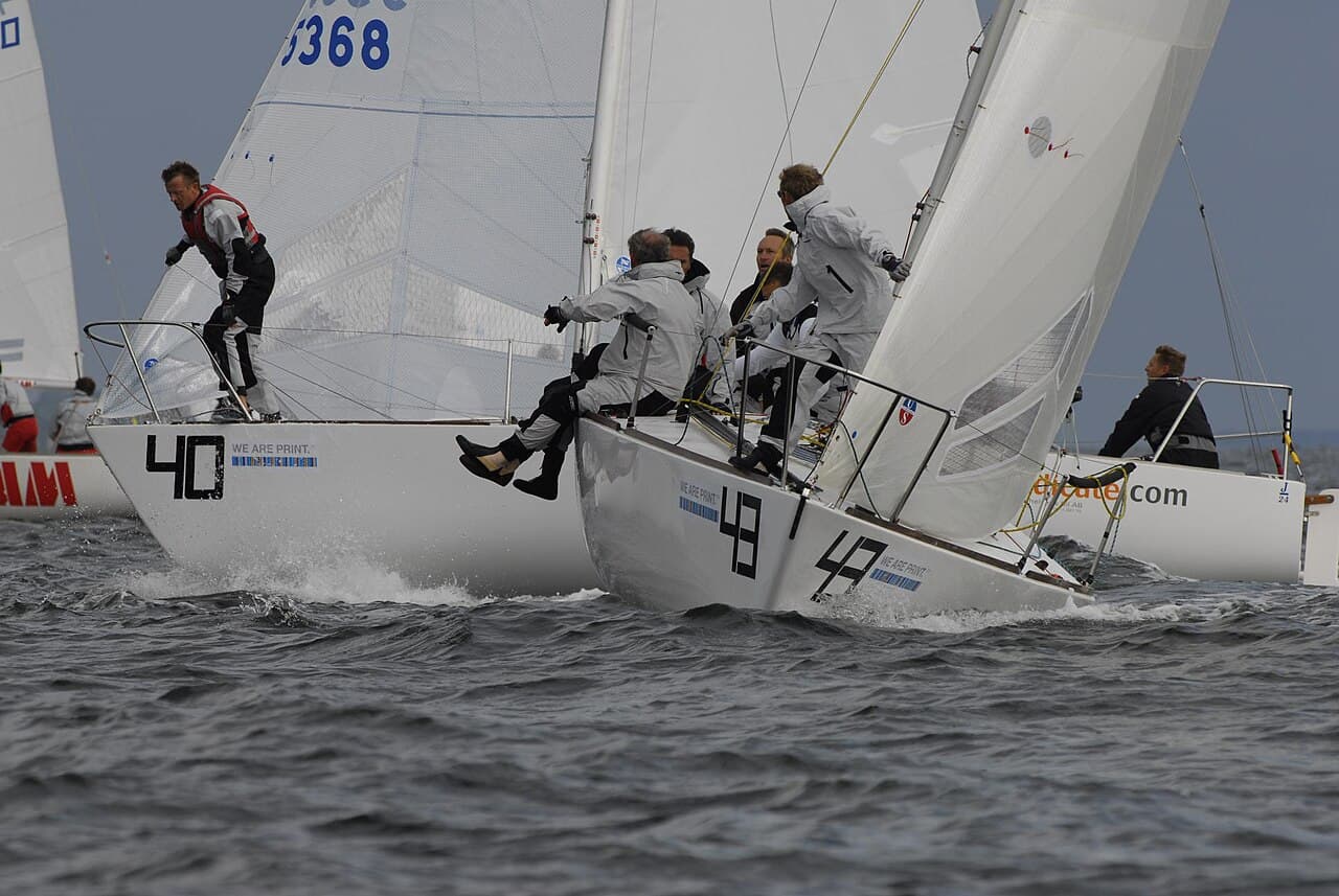
The canting keel: righting moment without the ballast penalty
The canting keel is the boat's central mechanism, and the physics is simple lever arithmetic. Righting moment is force times distance: RM = W × GZ, where W is the ballast weight and GZ is the horizontal distance from the boat's centre of gravity that the ballast acts through. A conventional fixed keel hangs its bulb straight down, so at rest the ballast contributes almost nothing to righting moment and only develops GZ as the whole boat heels. To add stability you add lead, which adds displacement and slows the boat — the trade-off a canting keel is designed to break.
Publicly the Melges 40 keel is a 3.4 m carbon fin (around 100 kg) carrying an 1,100 kg lead bulb, canting up to 45° each side — verify all three against class documentation. Swing that bulb to 45° and its centre of gravity shifts to windward by roughly the fin length times sin 45°, on the order of 2.4 m. Run the numbers: 1,100 kg acting through ~2.4 m is about 2,600 kgf·m — call it 26 kN·m — of added righting moment from the keel alone. For scale, the full crew (public max crew weight ~750 kg) hiking at roughly 1.7 m from centreline contributes only about 1,275 kgf·m. So the canted bulb is worth on the order of twice the entire crew on the rail. Those lever arms are approximate — the bulb's true CG height and the pivot geometry are boat-specific and must be verified — but the order of magnitude is the whole point.
More righting moment means the boat carries more sail and stays flatter for a given wind strength. A flatter hull keeps its foils at efficient angles of attack, presents the sail plan cleanly to the flow, and channels power into forward drive rather than heel and leeway. There is a subtlety worth flagging: a canted fin no longer works as a vertical lifting surface, so it stops generating side-force to resist leeway just when you need it upwind. The design answer is a single centreline canard daggerboard forward of the keel, dropped for upwind work to restore lateral plane while the keel is fully canted for stability. Upwind, then, the fin is typically canted hard to weather and the board is down; downwind crews trade keel angle against crew position to tune mode. Because the mechanism is powered — a Cariboni system, publicly a single hydraulic ram with a double-acting cylinder driven by a 24 V, ~4,500 W pump, derived from IMOCA and VO65 practice — its reliability is a speed issue, not merely a maintenance one. A keel that will not cant on cue, or cants slowly, forfeits the entire advantage, which is why keel hydraulics maintenance and the race yacht battery system sit directly on the performance critical path. The full mechanism is in canting keel explained.
Twin rudders: keeping the power controllable
Power is only an asset if the boat stays steerable, and that is where twin rudders earn their keep. A single centred rudder works well upright, but a beamy, powered-up hull heels hard and lifts its centreline clear of the surface — so a single blade can ventilate or stall exactly when boat speed peaks. Ventilation is the failure to understand here: under load, low pressure on the blade's suction side draws a cone of air down from the free surface along the stock. Air is about a thousand times less dense than water, so the moment it reaches the blade the lift collapses, the stern skids, and the boat rounds up. That is the classic high-speed broach, and it happens precisely in the conditions the rest of the boat is built to exploit.
Twin rudders defeat it geometrically. The blades are canted outboard so that, as the boat heels toward its working angle, the leeward blade rotates toward vertical and drops deeper — staying fully immersed and loaded — while the windward blade lifts near the surface and unloads. At the right heel the leeward rudder is close to vertical, so it is steering rather than trying to lift or dive the boat, and it never gets shallow enough to ventilate. The result is progressive, positive grip reaching and downwind, which is what lets owner-drivers press hard with the bow up instead of nervously feathering to keep the transom in. The cost is honest: two immersed high-aspect blades add wetted-surface drag over a single foil, and there is a small toe/alignment sensitivity, so the blades are finely faired and set with care. A nicked, fouled or misaligned rudder is a direct speed and control penalty. See twin rudders explained and hull and foil hydrodynamics.
Sails and the bowsprit: where the drive comes from
All that righting moment exists to be spent on sail power. The boat carries a fractional carbon rig with a square-topped (fat-head) mainsail; public figures give the main near 72 m², the jib near 49 m² and the gennaker around 200 m² — verify against the class sail plan. Those areas against a 3.17 m³ displaced volume work out to a sail-area-to-displacement ratio around 56 upwind and about 126 downwind — extreme power ratios that only a light, stiff, well-ballasted hull can carry. The square top is not styling: it loads the maximum roach area high, into the stronger, less sheared breeze aloft, and — because that head panel is cantilevered well aft of the mast on a diagonal head batten — it behaves as an automatic gust valve. When a puff hits, the pressure spike on the upper leech twists the head open to leeward, spilling and lowering the sail's centre of effort before the crew can react, then re-loading as the puff passes. The corollary is that in soft, shifty air the square top can hook closed and needs active mainsheet and vang work to keep it twisted correctly; it is not a set-and-forget shape.
Downwind and reaching, the retractable bowsprit projects the large asymmetric gennaker well forward of the bow. That buys two things. First, it moves the sail's luff into cleaner, less disturbed air ahead of the rig and jib wake, raising the sail's driving efficiency. Second, the longer base lets the boat sail hotter apparent-wind angles where an asymmetric makes its best lift-to-drag — the boat runs deep by sailing high and fast and gybing downwind, not by pointing dead downwind slowly. On a hull this light and this well-steered, a big well-projected asymmetric is exactly what produces the headline numbers: public sources cite downwind speeds of 22-24 knots in fresh breeze. That is decisive, because the classic displacement hull-speed limit for an 11.10 m waterline (1.34 × √LWL in feet) is only about 8 knots — so the boat routinely sails at nearly three times displacement hull speed, which is only possible off the back of full planing (see below). The interaction of rig, sails and airflow is developed in sail aerodynamics explained and the retractable bowsprit guide.
Planing hull form: early onto the plane, honest at speed
The hull shape ties the package together, and the governing parameter is the length Froude number, Fn = V / √(g·LWL). Below Fn ≈ 0.4 a hull is in displacement mode, dragging its own wave system; above ~0.4 it is semi-displacement; above Fn ≈ 1.0 it is fully planing, supported by dynamic pressure rather than buoyancy. Do the arithmetic on this boat: at 12 knots Fn is already about 0.6; at 16 knots about 0.8; at 20 knots about 1.0; at 23 knots about 1.1. In other words the Melges 40's normal downwind operating range sits right through and beyond the planing threshold — it is not flirting with the transition, it lives past it.
Getting there early is a shape decision. The Melges 40 is relatively narrow with flat aft sections, so once the boat is powered up and heeled, those flat run sections present a small effective angle of attack to the flow and generate hydrodynamic lift like a low-aspect planing surface. As speed rises the lift grows, the hull rises and trims, wetted surface and therefore viscous drag fall, and buoyant support converges toward zero — the boat stops pushing water aside and starts skimming over it. Combined with the ultralight displacement, that means it planes early and keeps accelerating rather than piling into a wave-making wall around Fn ≈ 1.0. The narrow beam is a deliberate light-air hedge: it keeps upright wetted surface and drag modest when the boat is not planing, and because righting moment comes from the canting keel rather than from form stability, the boat does not pay the light-air drag penalty a very wide, initially stiff hull would. The design reasoning behind these compromises is explored in race-boat design philosophy.
What separates two identical boats: execution
Here is the honest conclusion. In a strict one-design class the hull, rig, keel and sail plan are fixed across the fleet, so the hardware sets a shared ceiling — it cannot win the race for you. What separates identical boats is execution: forestay and shroud tension matched to the day, disciplined keel-cant and canard timing through every transition, crew weight placed and moved cleanly, faired and undamaged foils, reliable 24 V power and hydraulics, and manoeuvres that bleed the least speed. Good looks like a boat locked in its groove that changes gear early into gusts and lulls and exits tacks and gybes back at target speed and target VMG. Bad looks like a fast boat sailed in the wrong mode — over-heeled so the foils and rudders lose bite, under-trimmed so the square top stalls, or fumbling the keel-cant and board through the corners — giving back in the puffs exactly the speed the physics should be paying out.
That is the practical lesson for a serious sailor: speed is a system, and the crew is part of it. The design hands you a light, stiff, powerful, controllable platform sitting past the planing threshold whenever the breeze allows; the discipline you bring to trim, tuning, handling and maintenance decides how much of that potential reaches the water. For the whole boat, see the Melges 40 systems guide; for the wider set of speed and technique explainers, browse the Labs; and for the vocabulary used here, the sailing terms glossary.
Frequently asked questions
- Is the Melges 40 fast because it is light?
- Light displacement is necessary but not sufficient. Public figures put the boat near 3,250 kg lightship — verify against the class rules — which gives a displacement-to-length ratio around 66, deep in ultralight planing territory and roughly 800 kg under a Fast 40+. But low mass only pays if the structure is stiff enough to transmit rig and keel loads without flexing, and if there is enough righting moment to carry sail. On the Melges 40 the canting bulb, the carbon laminate stiffness and the 72/49/200 m² sail wardrobe are what convert saved kilograms into acceleration. Lightness sets the ceiling; the rest of the system reaches it.
- What is the single biggest speed factor on a Melges 40?
- In a strict one-design fleet the naval architecture is frozen, so execution is the largest variance. Every hull shares the same polar; sail trim, forestay and shroud tension, keel-cant timing, crew-weight placement, foil fairness and repeatable manoeuvres decide how close a crew sails to that polar. Two identical boats separate on mode discipline through transitions — holding target VMG, changing gear early into gusts, exiting tacks and gybes at speed — not on hardware. The boat rewards crews who keep it locked in the groove and punishes those who let it over-heel or under-trim.
- How does the canting keel actually make the boat faster?
- Righting moment scales with the horizontal lever arm of the ballast, RM = weight × arm. Canting the 1,100 kg lead bulb to 45° swings its centre of gravity roughly 2.4 m to windward (lever ≈ fin length × sin45°), adding on the order of 2,600 kgf·m of righting moment — approximately double what the full 750 kg crew contributes on the rail. Treat those lever figures as approximate and verify against class documentation. That extra moment lets the boat stand up under a huge sail plan and stay flat, so power goes into forward drive instead of heel and leeway. It is Grand Prix righting moment without the displacement penalty of a heavy fixed keel.
- Can a Melges 40 race offshore?
- It is engineered as an inshore and coastal Grand Prix weapon for windward-leeward and short-course racing, not ocean passages. Any offshore use depends entirely on the event, its OSR safety category, the boat's preparation and the crew's experience. The very features that make it quick — ultralight displacement, a powered canting keel dependent on a 24 V hydraulic system, and early planing — favour closed-course racing where the keel actuator, batteries and structure are monitored between short races rather than driven hard through a seaway for days.
- Why does it need twin rudders?
- A beamy, powered-up hull heels and lifts its centreline clear of the water, so a single centred blade can ventilate — draw air down from the surface, where density drops by roughly 1000× and the foil loses grip — exactly at peak boat speed, which is how boats broach. Twin rudders are canted outboard so the leeward blade stands vertical and stays fully immersed at working heel while the windward blade lifts clear. That gives progressive, positive steering grip reaching and downwind. It is what lets owner-drivers push at 20-plus knots with the bow up instead of feathering to keep the stern in. Without it the power the keel and sails create would be unusable in a breeze.
Related articles
How a Melges 40 Canting Keel Works
The Melges 40's canting keel trades ballast for lever arm: swing a ~1,100 kg bulb up to 45° to weather and the transverse ballast moment scales with sin(cant), so the boat carries roughly a third more sail area for the same heel. This is the physics, the load path through the keel pin and hydraulic ram, the leeway penalty the centreline canard exists to cover, and the failure modes the maintenance regime is built around.
Read the articleThe Complete Melges 40 Systems Guide
The Melges 40 is a canting-keel, twin-rudder, retractable-bowsprit one-design built by Premier Composite Technologies to a Botín design. This hub explains the engineering — the Cariboni hydraulics, the ECsix rig, the sandwich load paths — and how the systems interlock.
Read the articleRace Boat Electronics: What You Actually Need
A performance keelboat's electronics are a sensor-fusion problem, not a shopping list. This is the engineering: how apparent wind is measured and motion-corrected, how the true-wind vector is solved and calibrated for upwash and leeway, how boat speed is derived and trued against GPS, and how the whole system is networked and powered so the numbers stay trustworthy under load.
Read the article